Introduction
Torque and torsion are two fundamental concepts in mechanics and engineering that are often associated with rotational motion or deformation, although they differ considerably in definition and application. Understanding their roles within different mechanical systems requires an in-depth knowledge of these terms.
Torque refers to the force or moment which causes an object to rotate or alter its rotational motion, commonly found in rotating systems such as engines, motors and machinery. Torque plays a pivotal role in transmitting power, initiating motion and controlling its speed and direction of rotation. Torsion refers to the twisting or rotational deformation experienced by structural elements when exposed to torsional forces, often inducing twisting motion along an object’s longitudinal axis.
Torsion has great relevance in structural engineering where it is used to analyze beams, shafts, and other components under twisting forces and evaluate how this forces affect stability, load distribution and overall system performance. By delving deeper into these topics we will gain a comprehensive knowledge base regarding torque and torsion’s key aspects and implications within these fields of study.
Definition of torque
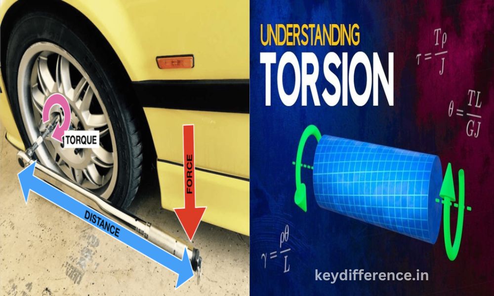
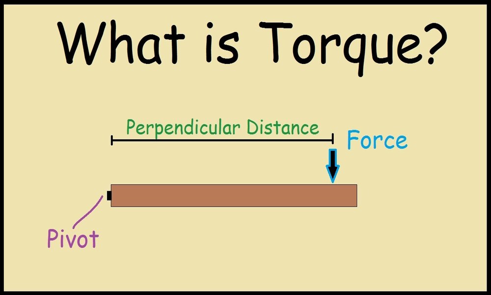
Torque in physics refers to the rotational equivalent of linear force; it measures how a force affects rotation around an axis. Calculation for torque involves multiplying force by distance from where force was applied; its symbol is “t”, while its SI unit is newton meters (Nm). Torque can be used to open doors, tighten wrenches and start cars. Furthermore, torque plays an essential role in numerous machines like engines and electric motors.
Here are some examples of torque:
When opening a door, you are applying torque to its doorknob. Your hand’s force multiplied by distance from doorknob to hinges results in torque that causes rotation of the door.
When using a wrench to turn a bolt, you are applying torque.
The force of your hand multiplied by its distance from the wrench is what causes its rotation; in other words, torque.
Start a car, and its engine applies torque to its wheels – this torque multiplied by their distance from each other is what causes them to spin. Torque is an essential concept in both physics and engineering, used to understand how objects rotate as well as develop machines capable of rotating objects..
Physical interpretation of torque
Torque can be understood through physical means that help us grasp its effect on rotational motion. Here are a few aspects of its physical interpretation that highlight its usefulness:
Rotational Force: Torque can be thought of as a rotational force that causes objects to spin around an axis, similar to how linear forces cause linear motion; however, torque applies a twisting force that results in angular or rotational movement instead.
Moment Arm: Torque depends on the distance between the axis of rotation and where force is being applied, known as a moment arm or lever arm. As its length increases, so too does its torque-producing capability: this effect occurs because more perpendicular distance must be covered before any turning effect can take place.
The direction of Rotation: Torque is a vector quantity with magnitude and direction, determined by the right-hand rule, whereby curling your fingers towards the force direction and pointing your thumb in the opposite direction points toward where torque or rotation may result from it.
Torque and Angular Acceleration: Torque is directly linked with an object’s angular acceleration. According to Newton’s second law of rotational motion, the torque applied to an object equals its moment of inertia multiplied by its angular acceleration; this relationship underscores how torque influences how rapidly an object accelerates during rotational movement.
Balancing Torques: When in equilibrium, the sum of torques acting on an object should equal zero. This principle is crucial when multiple torques exist since their net torque determines the rotational state. Balancing torques enables us to analyze stability and equilibrium within rotating systems.
Understanding the physical interpretation of torque allows us to analyze and predict the rotational behavior of objects, design mechanisms that rely on torque, and solve issues related to rotating motion in various fields of study.
The formula for calculating torque
Torque can be calculated with a straightforward formula that takes into account the force applied and lever arm distance from the axis of rotation. Here is how:
At each point in a rotational process, torque must be equal to lever arm length plus force application distance; where F is force application distance or the amount of force applied at any one moment in time. F is the applied force. Within this formula, both r and F must be perpendicular. Torque can be calculated as the cross product between the lever arm vector and the force vector.
Note that torque units vary based on force and distance units used, such as Newton meters for SI systems; otherwise, it could be expressed as foot-pounds (ft*lb). To accurately pinpoint the direction of torque, one can use the right-hand rule: when the fingers of one hand curl in the direction of applied force and the thumb points towards the direction of torque production.
Torque calculations play an integral part in many applications, from analyzing objects’ rotational motions to designing mechanical systems and understanding rotating machinery behavior; as well as calculating efficiency for power transmission systems.
Units of torque
Torque can be measured using various units depending on the system of measurement used, with common examples including:
Newton-meter (N*m): This standard unit of torque in the International System of Units (SI) denotes the amount produced when one Newton of force is applied perpendicularly at one meter from an axis of rotation.
Foot-pound (ft*lb): This unit of measure is commonly employed in the United States and other nations following the Imperial system, and measures torque created when one pound of force is applied at one foot from an axis of rotation.
Dyne-centimeter (dyn*cm): This unit of measure is often employed in scientific and engineering applications. It represents the torque produced when applying one dyne (the unit of force in the CGS system) applied perpendicularly one centimeter from an axis of rotation.
Torque can also be expressed using units derived from force and distance, such as kilogram-force meter (kgf*m) or pound-force inch (lb*in). Conversion factors can help convert between different units of torque as necessary.
Choose an appropriate unit of torque depending on its application and measurement system, though regardless of this choice it remains an integral component of rotational motion analysis, being applied across fields as diverse as physics, engineering, automotive industry design, and machinery development.
Examples of torque in everyday life
Torque plays an essential part in daily life, from driving cars and boats to operating machinery and systems. Below are examples that showcase its application:
Opening a Door: By applying pressure to a door handle, torque is created that allows you to open it. The distance between its hinge and where you exert your force determines how much torque is necessary to overcome resistance and rotate it in turn.
Utilizing a wrench: When tightening or loosening bolts or nuts using a wrench, torque is applied. The longer its handle is, the greater its torque-generating capability will be for any given force applied; making turning fasteners easier overall.
Riding a bicycle: When pedaling a bicycle, torque plays a central role. By applying force to the pedals, torque is produced that drives the chain and rotates wheels – propelling forward your bicycle journey.
Use of a Screwdriver: When driving screws into materials using a screwdriver, torque must be applied in order to rotate the screw. The applied torque determines how effectively it penetrates the material.
Turning a Steering Wheel: By turning the steering wheel of a vehicle, torque is applied to its steering mechanism, altering wheel direction and controlling vehicle movement.
Utilizing a Can Opener: When operating a manual can opener, torque must be applied in order to move the cutting wheel around the can’s edge and gradually open it up. Torque allows this wheel to pierce through and gradually open the can.
Utilizing a torque wrench: In automotive maintenance, torque wrenches are used to tighten bolts and nuts at specific torque values for optimal fastening and to avoid over-tightening or under-tightening which could lead to mechanical failures.
Wind Turbines: Turbines rely on torque to transform wind energy into electrical energy, as the wind’s force creates a torque on their turbine blades that causes them to rotate and generate power via a generator.
These examples demonstrate how torque can be found in many aspects of our daily lives and devices. Understanding torque helps us operate mechanical systems efficiently, fasten components securely, and optimize rotational device performance.
Definition of Torsion
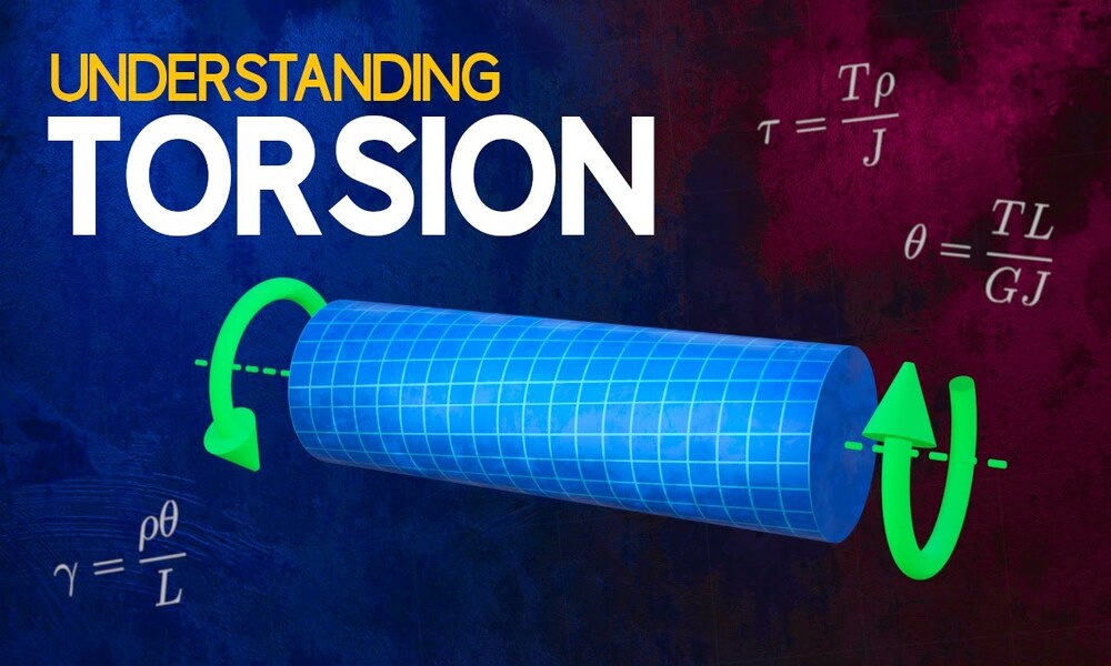
Torsion in physics refers to the twisting of an object due to an applied torque. Torsion can be expressed either using pascal (Pa), an SI unit for newtons per square meter or pounds per square inch (psi), while torque is expressed either using newton meters (N*m) or foot-pound force (ft*lbf).
Torsion stresses are measured perpendicularly across sections perpendicular to its torque axis and herar stress is produced along its radius.
Twisting can also result in warping, which results in transverse sections being out of alignment.
When unrestrained against warping, for shafts of uniform cross-section unrestrained against warping the torsion equation is as follows: * T is the Torsional Shear Stress (Pa), G Shear Modulus (Pa), J Polar Moment of Inertia (m4), Th Twist Angle (radians), L Length of the shaft in meters
Torsion is an everyday phenomenon in engineering applications, such as * Shafts in machines * Springs * Cables * Antennas
, and even Bones.
Torsion can be both beneficial and detrimental, depending on its application. For example, torsion may be used to transmit power through a shaft but its torque could cause it to buckle if applied in excess. Furthermore, stored energy stored through springs could experience too much torsion causing them to buckle under too much tension.
Physical interpretation of torsion
Torsion has a physical interpretation that helps us better comprehend its effect on structural elements and materials. Here are key aspects of its physical interpretation:
Twisting deformation: Torsion refers to the twisting deformation that occurs when structural elements are exposed to torque or twisting forces, such as torque applied via a torque wrench. A torque force induces shear stress across its cross-section which then leads to twisting or deforming along its longitudinal axis.
Torsional Stress: Torsion creates a type of strain in materials in structural elements through torsion. Torsional stress measures the resistance of materials against twisting forces and is distributed across their cross-section; its magnitude depends on the torque applied, the geometry of the object, and material properties.
Torsion in structural elements with circular cross-sections such as shafts or rods is most pronounced due to torque applied, as applying torque creates a shearing effect that rotates the cross-sections relative to each other and causes herniation of shear forces between cross-sections.
Torsional Rigidity or Stiffness of Material: Torsion resistance can be measured through the material’s torsional rigidity or stiffness; it determines how well a material resists twisting when subject to torque, with materials with higher rigidities showing less deformation and being capable of handling larger torque loads without excessive twisting.
Torsional Buckling: When subjected to excessive torsional forces, certain structural elements may experience torsional buckling – an instance in which an object loses stability and collapses as a result of twisting deformation exceeding its ability to resist torque-induced stresses.
Torsional Vibration: Torsional forces can lead to torsional vibration, an oscillatory motion of a structural element caused by alternate torques. Torsional vibration should be considered when designing machinery as it can have adverse effects on the performance, reliability, and lifespan of rotating systems.
Understanding the physical interpretation of torsion allows engineers and designers to assess the structural integrity of components, select materials suitable for torsional loads, and design structures capable of withstanding torsion forces. It is especially relevant when applied to shafts, beams, springs, or any other structural elements subjected to twisting or rotational forces.
The formula for calculating torsion
Torsion can be measured quantitatively using a torsion formula. The formula accounts for material properties as well as geometric considerations when calculating torsion; here is an example:
At any point in time, t = G * ph * r)/L This equation represents the torque applied to a structure as an act of torsion; G is its shear modulus or modulus of rigidity; L stands for length and is represented as Torsion Stress/Torque ratio
P is the angle of twist or the amount of rotation experienced by the structure; R is the radial distance from its center to the point of interest in its cross-section; L is its total length.
Shear modulus (G) is a material property that measures resistance to shearing forces in materials used for manufacture or repair, typically provided in material engineering data. It can vary according to each material type used and must always be specific to it in order for measurement purposes.
The angle of twist (ph) refers to the amount of rotation experienced by structures due to applied torsional stress. This measurement typically occurs along their length due to torque application and material properties as well as the length of the structure. It can either be expressed in degrees or radians and depends on other factors like applied torque, material properties, and length of the structure.
Radial distance (r) refers to the perpendicular distance from an object’s axis of rotation to its point of interest in its cross-section, defining both the lever arm for torsion force application as well as the magnitude of stress due to torsion.
Length (L) refers to the length over which torsional stress is applied and thus impacts its distribution as well as any subsequent deformation that might result. It’s an important variable as its influence impacts deformation rates as well as possible.
The torsion formula allows engineers and designers to analyze the torsional behavior of structural elements subjected to twisting forces. This enables engineers and designers to determine the maximum allowable torque, assess structural integrity and select suitable materials and dimensions for any given application.
Units of torsion
Torsion can be measured using units that convey its magnitude; such as twisting deformation and stress experienced by structural elements. Common measurements used for torsion measurement include:
Pascal (Pa): The Pascal unit of pressure in the International System of Units (SI). When applied to torsion, this can represent either torsional stress or shear stress; N/m2 stands for force per unit area.
Pound-force per square inch (psi): This unit of measurement is commonly employed in both the United States and other nations following the Imperial system, representing pressure or stress exerted through torsion, defined as force applied over an area of one square inch in pounds.
Newton-meter (N*m): While commonly associated with torque measurements, Newton-meter can also be used to quantify twisting moments or the internal forces generated from torsion within structures. In this sense, it represents the force necessary to twist an element through certain angles.
Dyne-centimeter (dyn*cm): The dyne-centimeter is a unit in the centimeter-gram-second (CGS) system and measures work done or energy used to twist an object through a certain angle.
Kilogram-force meter (kgf*m): This engineering unit is widely utilized, particularly in countries using the metric system. It represents the force necessary to twist an element with a lever arm of one meter.
These units serve to quantify the degree of torsional stress or deformation experienced by structural elements. Their selection depends upon your context, measurement system and engineering standards in use.
Examples of torsion in everyday life
Torsion is an everyday occurrence and here are a few examples that demonstrate its use:
Twisting Off a Jar Lid: To open a tightly sealed jar, apply a twisting force to its lid. This twisting force causes torsion within it and helps break open the seal for easy opening of the jar.
Applying Torque With a Screwdriver: When driving screws into materials using a screwdriver, torque must be applied to its handle to transfer to its shaft and twist the screw, enabling penetration through materials.
Opening and Closing Doors with Spring Hinges: Spring hinges are commonly utilized on self-closing doors. They utilize torsion springs that store energy as you open and release it automatically when closing the door, providing necessary twisting forces for closure.
Torsion Bar Suspension in Vehicles: Torsion bar suspension systems are widely utilized in cars to provide a smooth ride, using metal bars which flex under the weight of the vehicle and twist, creating torsion and damping road shocks.
Use of a mechanical watch: Mechanical watches use a mainspring that stores potential energy. As soon as this potential energy is released from storage by unwinding of the mainspring, gears transmit it and create torsion in the watch hands that turn and indicate time.
Torsion in Structural Beams: Buildings and bridges often use structural beams that experience torsion due to various loads and forces, including wind forces or asymmetric loading conditions, where torsion can cause them to twist along their longitudinal axis and become deformed. This phenomenon can result in buildings collapsing, as well as bridges collapsing.
Torsion in Sports Equipment: Torsion can be found throughout various sports equipment. When golfers swing their clubs, torsion occurs in the shaft allowing energy transfer from swinging the club onto the golf ball. Tennis players also experience torsion when striking balls with a racquet; this causes it to twist.
Utilizing Torsion Springs in Garage Doors: Torsion springs are used extensively in garage doors to counterbalance the weight of door panels and to store energy when raised up and release it when closed down, making opening and closing simpler with either manual operation or motorized openers.
These examples demonstrate how torsion can be found everywhere we turn in daily life, making its presence all-pervasive and essential to understanding its dynamics and applications in designing structures and objects that experience twisting forces, such as bridges or vehicles that experience torsion, while providing crucial data regarding their stability, functionality, and efficiency.
Comparison Table of Torque and Torsion
Here is a comparison table highlighting the key differences between torque and torsion:
| Aspect | Torque | Torsion |
|---|---|---|
| Definition | Torque is a measure of the force that can cause an object to rotate around an axis. It is the product of the applied force and the lever arm distance. | Torsion refers to the twisting deformation experienced by a structural element when subjected to a torque or twisting force. It involves the rotation or twisting of an object along its longitudinal axis. |
| Type of Quantity | Torque is a vector quantity as it has both magnitude and direction. | Torsion is a type of deformation, which is a scalar quantity that measures the degree of twisting. |
| Physical Interpretation | Torque describes the rotational force or moment that can cause an object to rotate or change its rotational motion. | Torsion describes the twisting or rotational deformation that occurs in a structural element when subjected to a torsional force. It relates to the resistance of the material to twisting. |
| Calculation Formula | Torque (τ) = r × F, where r is the lever arm distance and F is the applied force. | Torsion is not calculated directly. It is a deformation phenomenon that is analyzed through stress and strain calculations using material properties and geometric characteristics of the structure. |
| Units | Torque is typically measured in units such as Newton-meter (N·m) or foot-pound (ft·lb), depending on the system of measurement. | Torsion is measured in units such as Pascal (Pa) or pound-force per square inch (psi), which represent torsional stress or shear stress. |
| Application | Torque is commonly encountered in rotating systems, machinery, and mechanical devices where rotational motion or force is involved. It is used to analyze and design rotational components and systems. | Torsion is particularly relevant in structural engineering, where it is used to analyze the behavior of beams, shafts, and other structural elements subjected to twisting forces. It helps in assessing structural integrity and designing torsion-resistant structures. |
Understanding the differences between torque and torsion helps in distinguishing their respective roles and applications in various fields, ranging from mechanics and engineering to structural design and material science.
Similarities between Torque and Torsion
Torsion and torque each have unique definitions and applications; however, there are certain similarities between the two concepts that may make their understanding easier. Here are a few:
Rotational Movement: Torsion and torque both fall under the category of rotational motion, meaning twisting or rotating around an axis.
Deformation: Both torque and torsion cause deformation to objects or materials they act upon, either through rotational motion or changes, or twisting or rotational deformation in structural elements.
Force and Moment: Both torque and torsion involve applying force or moment, though their definitions differ significantly: torque measures the force that causes rotational movement; torsion refers to twisting forces applied that induce deformation by twisting.
Cross-Sectional Considerations: Both torque and torsion take into account the properties of an object or structural element’s cross-section, with torque measuring lever arm distance perpendicular to force vector and torsion spreading its stress evenly across its cross-section.
Material Response: Torsion and torque both have an effect on materials’ behavior. Torque measures the material’s response to rotational motion while in torsion its resistance to twisting deformation is considered, taking into account factors like shear modulus and torsional rigidity.
Engineering Analysis: Torque and torsion are considered fundamental concepts in mechanical design, while torsion has an integral part to play in structural engineering for analyzing components’ behavior under twisting forces.
Torque and torsion may have some similar aspects, yet it is essential to recognize their distinct definitions, applications, and contexts of use. Acknowledging their similarities and differences helps individuals utilize and analyze these concepts effectively in their fields of endeavor and applications.
Influence on mechanical systems
Torsion and torque exert significant influences on mechanical systems. Here are their primary effects:
Rotational Motion: The torque is directly responsible for initiating and controlling rotational motion in mechanical systems. By applying torque to rotating components such as motors or engines, they can be set into motion or their speed and direction altered with ease.
Torsion, on the other hand, affects structural elements’ rotational behavior by inducing twisting deformation that compromises their stability and performance – both processes which provide torque control of rotation.
Power Transmission: Torque plays an integral part in power transmission within mechanical systems. For instance, engines rely on combustion torque being transferred directly from the combustion process to the crankshaft which then drives the transmission system and eventually wheels.
Torsion forces also have their place, particularly within shafts or gears where twisting forces must be transmitted efficiently and reliably.
Mechanical Stability: Torque and torsion have a profound effect on mechanical systems’ stability and structural integrity, such as rotating machinery.
Excessive torque can cause mechanical failure through shearing of bolts or distortion of components; excessive torsion forces may twist structural elements past their limits causing deformation or failure. Therefore, proper analysis and design considerations for torque and torsion must be undertaken to ensure the longevity and resilience of mechanical systems.
Component Design: Torque and torsion play an essential role in designing mechanical components. Shafts, bearings and couplings used in rotating systems such as motors or turbines must meet torque requirements to operate efficiently and reliably, while structural elements like beams and columns need to be constructed so as to withstand torsion loads and prevent any deformation or buckling that can occur due to torsion loads.
Load Distribution: Torque and torsion have an effect on how loads are distributed within mechanical systems. Torque distribution must be carefully managed in rotating machinery to avoid overloading any specific component; in structural elements like bearings and beams, tension distribution will determine areas with increased or decreased stress concentrations within each component.
System Performance: Torque and torsion can have a tremendous effect on mechanical systems’ overall performance, such as vehicles’ acceleration, towing capacity, and fuel economy; suspension systems’ torsion impacts ride comfort, stability, and handling. Therefore, managing and controlling these aspects are integral parts of optimizing mechanical system functionality.
Engineers and designers need a deep knowledge of torque and torsion effects on mechanical systems in order to ensure safe and efficient operation, optimize performance and extend lifespan. Proper analysis, component selection, and design considerations related to torque and torsion contribute significantly to reliability and functionality in mechanical systems.
Conclusion
Torque and torsion are two related concepts that play an essential role in various aspects of mechanics and engineering. Torque describes the rotational force or moment that causes objects to rotate or change their rotational motion; it is commonly found in mechanical devices.
Torsion on the other hand refers to twisting deformation that occurs in structural elements when subjected to twisting forces such as torque. Torsion analysis has particular relevance in structural engineering as it allows engineers to assess beams, shafts, and other structures exposed to twisting forces.