Introduction of Thevenin and Norton
The Norton and Thevenin theorems can be used as circuit analysis techniques to simplify complex circuits. The two theorems can be used to replace complex circuits with simpler equivalent circuits that have the same effect.
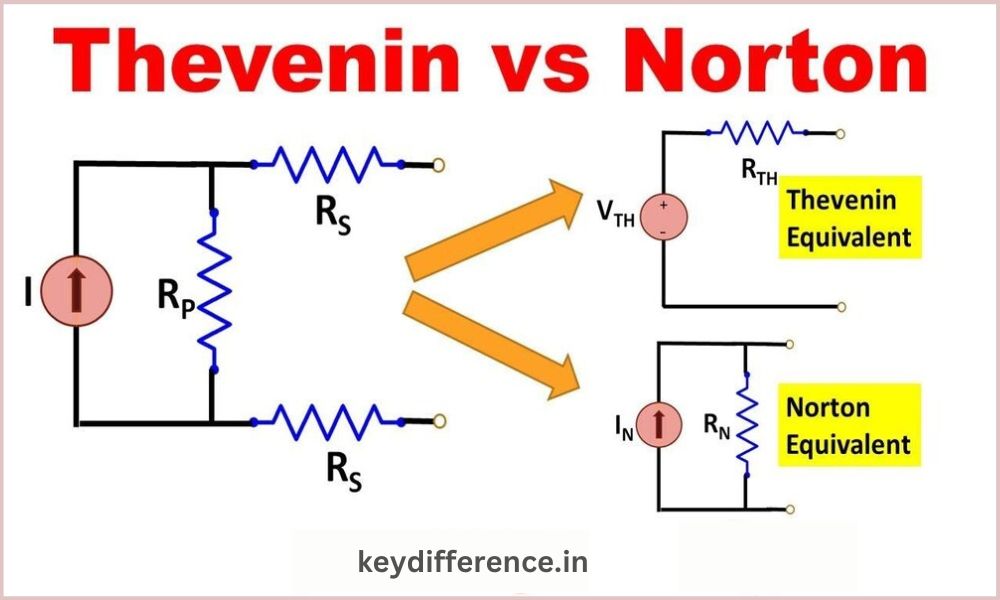
Thevenin’s Theorem is based on a voltage source connected in series to a resistance, whereas Norton’s Theorem relies on a current source coupled in parallel to a resistance.
Thevenin’s Theorem states any linear circuit may be replaced by an equivalent circuit consisting of a voltage source connected in series to a resistor. The Thevenin voltage represents the voltage in open circuit across the terminals on the original circuit. Thevenin resistance is a resistance measured by looking at the terminals with the original circuit.
Norton’s Theorem says that any linear circuit is replaceable with an equivalent circuit consisting of a current source and a resistor in parallel. The Norton current is a short circuit through the terminals in the original circuit. The Norton resistance is a resistance measured by looking at the terminals with the original circuit.
The Thevenin equivalent circuit and Norton equivalent are the same. The Thevenin voltage equals the Norton current multiplied by the Norton resistance. The Thevenin resistance equals the Norton resistance divided by Norton current.
Thevenin’s Theorem can be used more easily when the circuit has voltage sources. Norton’s Theorem, on the other hand, is easier to apply when the circuit contains current sources. Both theorems can be used to simplify any linear system.
What is Thevenin?
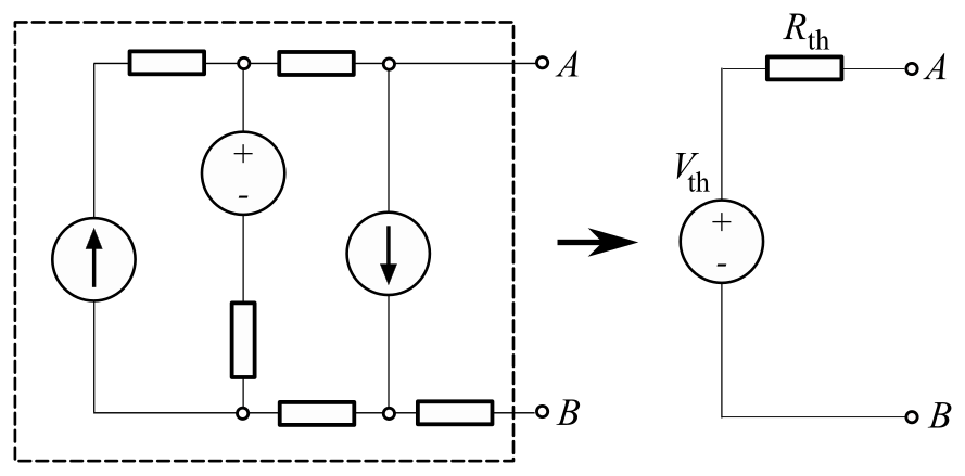
Thevenin’s Theorem is an important theorem for circuit analysis. It states that any linear system can be replaced by an equivalent circuit consisting of a voltage source connected in series to a resistor. The Thevenin voltage represents the voltage in open circuit across the terminals on the original circuit. The Thevenin resistance represents the resistance as seen when looking at the terminals.
Thevenin’s Theorem is useful for simplifying complex circuits, and to help analyze the effects that changes in the circuit have.
Thevenin’s theorem was named after Leon Charles Thevenin. A French electrical engineer, Thevenin published the first version of the theorem back in 1883.
The following are the steps to applying Thevenin’s Theorem.
- Replace the load resistor with an open-circuit.
- Calculate the Thevenin Voltage – the voltage across an open circuit. 3. Replace the power source. Replace all voltage sources with short circuits and all current sources with open circuits. 4. Calculate the Thevenin Resistance – the total resistance between open circuit connection points once all sources have been removed.
- Replace the open circuit by the Thevenin equivalent circuit.
The Thevenin equivalent Circuit can be used to analyse the effects of circuit changes.
What is Norton?
The Norton theorem, a circuit analysis theorem, states that any linear system can be replaced by an equivalent circuit consisting of a current source and a resistor in parallel. The Norton current is a short-circuit through the terminals in the original circuit. The Norton resistance is a resistance that is seen when looking at the terminals with the original circuit.
The Norton’s theorem is a useful tool for simplifying complex circuits, and for analyzing the effects of circuit changes.
Edward Lawry Norton is an American electrical engineering who published Norton’s Theorem first in 1926.
The steps to applying Norton’s theorem are as follows:
- Replace the load resistor with a circuit short.
- Calculate the Norton Current – the current flowing through the short circuit.
- Replace the power source. Replace all voltage sources with open circuits and replace all current sources with short circuits.
- Calculate the Norton Resistance – the total resistance between short circuit connection points once all sources have been removed.
- Replace the short circuit by the Norton equivalent circuit.
You can use the Norton equivalent circuit to analyse the effect of circuit changes.
The Thevenin theorem and Norton’s Theorem are essentially identical. The Thevenin voltage equals the Norton current multiplied with the Norton resistance. The Thevenin resistance equals the Norton resistance divided by Norton current.
The Theorem of Thevenin is easier to apply when the circuit has voltage sources. Both theorems are able to simplify any linear system.
Thevenin’s Theorem
Thevenin’s Theorem is an important theorem for circuit analysis. It states that any linear system can be replaced by an equivalent circuit consisting of a voltage source connected in series to a resistor. The Thevenin voltage represents the voltage in open circuit across the terminals on the original circuit. The Thevenin resistance is a resistance measured by looking at the terminals.
Thevenin’s Theorem is useful for simplifying complex circuits, and analyzing the effects of circuit changes.
Thevenin’s theorem was named after Leon Charles Thevenin. A French electrical engineer, Thevenin published the first version of the theorem back in 1883.
The following are the steps to applying Thevenin’s Theorem.
- Replace the load resistor with an open-circuit.
- Calculate the Thevenin Voltage – the voltage across an open circuit. 3. Replace the power source. Replace all voltage sources with short circuits and all current sources with open circuits. 4. Calculate the Thevenin Resistance – the total resistance between open circuit connection points once all sources have been removed.
- Replace the open circuit by the Thevenin equivalent circuit.
Norton’s Theorem
The Norton theorem, a circuit analysis theorem, states that any linear system can be replaced by an equivalent circuit consisting of a current source and a resistor in parallel. The Norton current is a short-circuit through the terminals in the original circuit. The Norton resistance is a resistance that is seen when looking at the terminals with the original circuit.
The Norton’s Theorem is a useful tool for simplifying complex circuits, and analyzing the effects of circuit changes.
Edward Lawry Norton is an American electrical engineering who published Norton’s Theorem first in 1926.
The steps to applying Norton’s theorem are as follows:
- Replace the load resistor with a circuit short.
- Calculate the Norton Current – the current flowing through the short circuit.
- Replace the power source. Replace all voltage sources with open circuits and replace all current sources with short circuits.
- Calculate the Norton Resistance – the total resistance between short circuit connection points once all sources have been removed.
- Replace the short circuit by the Norton equivalent circuit.
You can use the Norton equivalent circuit to analyse the effect of circuit changes.
The Thevenin theorem and Norton’s Theorem are essentially identical. The Thevenin voltage equals the Norton current multiplied with the Norton resistance. The Thevenin resistance equals the Norton resistance divided with the Norton current.
The Theorem of Thevenin is easier to apply when the circuit has voltage sources. Both theorems are able to simplify any linear system.
Comparison Table of Thevenin and Norton
Here is a table comparing Thevenin’s and Norton’s theorems:
| Features | Thevenin | Norton |
|---|---|---|
| Components | Voltage source connected in series with resistor | Parallel connection of a current source and a resistor |
| Equivalent circuit | Voltage source with resistor | Current source and resistor |
| Calculation of Thevenin Voltage | Open-circuit voltage across terminals of original circuit | Short-circuiting current through the terminals on the original circuit |
| Calculation of Thevenin Resistance | The resistance between the connection points of an open circuit after all sources are removed | The total resistance between the connection points of the short circuit after all sources are removed |
| Relationship between Thevenin & Norton | The Thevenin voltage equals the Norton voltage multiplied by Norton resistance and the Thevenin resistence equals the Norton resistance divided dividing by Norton current | |
| Easy of Use | It is usually easier to use if the original circuit has voltage sources | It is usually easier to use the circuit when it contains current sources |
The Thevenin and Norton Theorems can be powerful tools to simplify circuits that are complex and make it easier to analyse the effects of circuit changes.
The easiest theorem to use depends on the circuit being analyzed.
Relationship Between Thevenin and Norton Equivalent Circuits
The Norton and Thevenin theorems can be used as circuit analysis techniques to simplify complex circuits. The two theorems can be used to replace complex circuits with simpler equivalent circuits that have the same effect.
Thevenin’s Theorem is based on a voltage source connected in series to a resistance, while Norton’s Theorem relies on a current source coupled in parallel to a resistance.
The Thevenin equivalent circuit and Norton equivalent are the same. The Thevenin voltage equals the Norton current multiplied with the Norton resistance. The Thevenin resistance equals the Norton resistance divided with the Norton current.
If you have a Thevenin circuit, then you can easily find the Norton equivalent circuit. You do this by dividing the Thevenin current by the Thevenin resistor, and using the result as the Norton current source. If you have a Norton circuit, you can get the Thevenin equivalent by multiplying the Norton voltage by the Norton resistance and using this value as the voltage of the Thevenin voltage.
It is easy to convert between Thevenin equivalent circuits and Norton equivalents, which is useful when dealing with complex circuits.
Advantages and Disadvantages of Thevenin and Norton Theorems
The Norton and Thevenin theorems can be used as circuit analysis techniques to simplify complex circuits. The two theorems can be used to replace complex circuits with simpler equivalent circuits that have the same effect.
Thevenin’s Theorem is based on a voltage source connected in series to a resistance, while Norton’s Theorem relies on a current source coupled in parallel to a resistance.
The Thevenin equivalent circuit and Norton equivalent are the same. The Thevenin voltage equals the Norton current multiplied with the Norton resistance. The Thevenin resistance equals the Norton resistance divided with the Norton current.
If you have a Thevenin circuit, then you can easily find the Norton equivalent circuit. You do this by dividing the Thevenin current by the Thevenin resistor, and using the result as the Norton current source. If you have a Norton circuit, you can get the Thevenin equivalent by multiplying the Norton voltage by the Norton resistance and using this value as the voltage of the Thevenin voltage.
It is easy to convert between Thevenin equivalent circuits and Norton equivalents, which is useful when dealing with complex circuits.
Maximum power transfer theorem
According to the maximum-power-transfer (MPT) theorem, maximum power can transfer between a source of power and a load if the resistance of a load is equal to the resistance of a source.
This is an explanation for the following theorem:
- If the load resistance is equal to the source resistance then the voltage at a source equals that across the load.
- The source voltage is applied at full power to the load.
- To find the current flowing, divide the voltage across the load (the load) by its resistance.
- The current flowing from the source and through the load is equal.
- Power dissipated equals voltage multiplied with current in the load.
- The amount of power supplied by a source is equal to the amount of power dissipated within the load.
When the resistance between the source and load is greater, the load will be less powerful. Neither the voltage across the source nor the voltage across the loads are the same.
This theorem can be useful when designing circuits to transfer maximum power from a source to a load. For example, it can be used to design electronic devices like amplifiers, power supplies, and other devices.