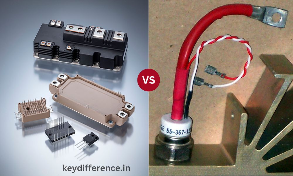
Power semiconductors play an essential role in modern electrical and electronic systems they allow efficient management and transformation of electric power. Two of the most prominent devices that fall into this class include two the Insulated Gate Bipolar Transistor (IGBT) and the Thyristor (SCR – Silicon Controlled Rectifier).
Knowing the distinctions between the two devices is vital for both engineers and those interested in the area of power electronics. This outline of content provides an overview of these differences, allowing readers to make educated choices when choosing the right device for their needs.
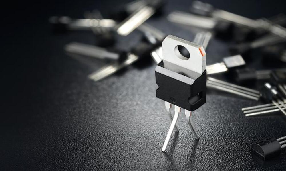
What is IGBT?
IGBT stands for Insulated Gate Bipolar Transistor. This power semiconductor device combines the advantages of both MOSFET (Metal-Oxide-Semiconductor Field-Effect Transistor) and bipolar junction transistor (BJT).IGBTs are specifically designed to handle higher power levels efficiently while simultaneously controlling switching and control functions efficiently in various applications where switching/control is essential.
An IGBT’s structure consists of three major regions: the N+ collector, the P-well drift region, and the N+ emitter. Each of these areas connects to either positive or negative terminals of its respective power supply while P-well acts as a buffer between collector and emitter regions.
An IGBT works by controlling the flow of current between its collector and emitter by applying a voltage at its gate terminal, which in turn regulates the conductivity of its N-channel, thus regulating current flow. If this gate voltage is high enough, IGBTs become “on”, permitting current to flow freely; when this threshold decreases to low enough values they become “off”, blocking current flow.
IGBTs offer several features and advantages, such as:
- High switching frequency capability: IGBTs have an impressively fast switching rate, making them suitable for applications requiring high-frequency switching.
- Low conduction losses: IGBTs feature low on-state voltage drops that reduce power losses during conduction.
- Fast on and off times: IGBTs offer faster switching speeds compared to thyristors, providing for efficient power control. They also feature high power handling capacities suitable for higher voltage/current applications.
- Voltage and Current Ratings: IGBTs come with various voltage and current ratings to meet various applications’ specific requirements.
IGBTs find numerous uses in various fields, including motor drives and control systems, power supplies, renewable energy systems (such as solar inverters and wind turbines ) as well as industrial and automotive applications.
IGBTs also come with limitations and disadvantages, including needing complex driving circuitry to control them properly, limited voltage blocking capability compared to thyristors, and relatively higher costs. When choosing between power semiconductor devices for specific applications these factors must be taken into account.
What is Thyristor?
A Silicon Controlled Rectifier (SCR), more specifically, is a four-layer semiconductor device used as an on/off switch in high-power applications. It allows only one direction of current to flow and can be activated via control signals to conduct.
Thyristors consist of three main regions: P-type anode, N-type cathode, and P-type control gate – these components are connected in series for use as a three-terminal device with one serving as the trigger terminal to switch on and initiate conduction.
Thyristor operation relies on an effect known as “latching.” When turned off, no current is flowing through it, so its non-conductive state needs to be broken in some way by applying a positive voltage pulse across its control gate and cathode connections; this causes conduction to begin, with current flowing freely through it until its forward current falls below a certain threshold value or external circuitry is used to forcibly turn it off.
Thyristors offer many features and benefits, such as:
Thyristors offer excellent voltage-blocking capability, making them suitable for high-power applications. Furthermore, their simple driving circuitry makes triggering and turning off relatively effortless. Thyristors feature low on-state voltage drops due to low conduction losses, leading to improved efficiency. Furthermore, their high power handling capacity makes them ideal for power control applications such as lighting controls.
Current Ratings and Conduction Losses: Thyristors come in various current ratings to meet various application needs.
Thyristors find use in AC and DC power control, voltage regulation and power factor correction, battery charging/discharging processes, as well as heating/lighting systems.
Thyristors also come with several limitations and disadvantages that should be taken into consideration when selecting the suitable power semiconductor device for an application, such as limited switching frequency capabilities, longer turn-off times, inability to control output once turned on, and high harmonic distortion rates.When making this decision it is essential to carefully assess all available factors when making an informed choice about power semiconductor devices.
Comparison Table of IGBT and Thyristor
Here’s a comparison table highlighting the key differences between IGBT and Thyristor:
| Aspect | IGBT | Thyristor (SCR) |
|---|---|---|
| Structure | Combination of MOSFET and BJT | Four-layer semiconductor device (SCR) |
| Operation | Switching device | Controlled switch |
| Current Flow | Bidirectional | Unidirectional |
| Control | Gate voltage control | Triggering voltage control |
| Switching Speed | Fast | Relatively slower |
| Switching Frequency | High | Limited |
| Turn-On Time | Fast | Moderate to slow |
| Turn-Off Time | Fast | Moderate to slow |
| Voltage Blocking | Limited voltage-blocking capability | High voltage blocking capability |
| Conduction Losses | Low | Low |
| Power Handling | High power handling capacity | High power handling capacity |
| Control Flexibility | Can control output during conduction | Cannot control output once triggered |
| Applications | Motor drives, power supplies, renewable energy systems, industrial and automotive applications | AC and DC power control, voltage regulation, battery charging, heating and lighting systems |
| Driving Circuitry | Complex | Relatively simple |
| Cost | Relatively higher | Relatively lower |
It’s important to note that while IGBTs excel in high-frequency switching and flexible control, thyristors are preferred for high-voltage blocking and simplicity of driving circuitry.
The choice between IGBT and Thyristor depends on the specific requirements and characteristics of the power control application at hand.
Voltage regulation and power factor correction
Voltage regulation and power factor correction are two integral aspects of power management in electrical systems.
Let’s briefly cover each concept here:
Voltage Regulation:
Voltage regulation refers to the practice of keeping voltage within acceptable limits regardless of changes to input voltage or load changes, so as to maintain stable voltage supply for electrical devices and equipment that rely on reliable voltage sources – fluctuation can lead to performance issues, damage or premature failure if left uncontrolled.
Power Factor Correction (PFC):
A power factor measures how efficiently electrical energy is being utilized within an application system, measuring it as the ratio between real power (measured in kilowatts) and apparent power (kilovolt-amperes).
Ineffective use of electricity leads to increased consumption, higher utility bills and strain on its distribution system. A low power factor indicates poor utilization.Voltage regulation and power factor correction are integral parts of maintaining an efficient electrical system. By maintaining stable voltage levels and increasing power factor values, these techniques help optimize energy usage while simultaneously minimizing losses and optimizing the overall performance of equipment and distribution networks.
Battery charging and discharging
Battery charging and discharging are Essential processes in operating Battery systems, so let’s look more closely at these Processes:
Charging:
Battery charging is the process of Replenishing energy stored within batteries after they have been Discharged during use and converted to Electrical energy by chemical Reactions within them. An external power source must then be connected in order to reverse these chemical reactions and restore its energy capacity.
- Constant Current (CC) Charging: At this stage, a constant current is provided to the battery until it reaches a predefined voltage threshold. Constant current charging allows for faster initial charges as the battery can accommodate higher current charges at lower voltage levels.
- Constant Voltage Charging (CV): Once the predefined voltage threshold has been met, the charger switches into constant voltage mode, whereby it maintains a constant voltage while decreasing charging current progressively until fully charging occurs. The rate at which a battery charges is also gradual until fully charged occurs.
Notably, different battery chemistries each have unique charging requirements and limitations that should be observed to ensure safe and optimal charging results. When it comes to batteries it’s crucial that manufacturers provide guidance for safe charging if possible.
Battery Discharging:
Battery discharging refers to the practice of using stored energy from batteries to power devices or systems. When connected to a load, current flows from them and gradually lowers battery voltage over time.
To maximize battery performance and longevity, it is critical that proper charging and discharging practices be adopted, including avoiding overcharging or over-discharging and operating within recommended voltage and current limits.
Battery Management Systems (BMSs) are often employed to monitor and regulate the charging and discharging processes of batteries, assuring optimal utilization, protection, and longevity through various algorithms, safety mechanisms, and balancing techniques. These BMSs help ensure optimal utilization, protection, and longevity.
Limitations and disadvantages
Both IGBTs and Thyristors possess certain limitations and drawbacks that should be considered when selecting power semiconductor devices for any specific application.
Let’s go over these differences individually:
Limitations and Disadvantages of IGBTs:
- Complex Driving Circuitry: IGBTs require more complex driving circuitry compared to other power semiconductor devices due to the necessity of controlling gate voltage and maintaining proper switching characteristics.
- Limitation on Voltage Blocking Capability: IGBTs have limited voltage-blocking capacities compared with devices such as thyristors. As such, they may not be suitable for applications requiring high voltage blocking capacities.
- Relatively Higher Cost: IGBTs typically tend to be more costly than other power semiconductor devices like MOSFETs or BJTs, which may increase overall system costs, particularly when multiple IGBTs are required in an application.
Limitations and Disadvantages of Thyristors (SCRs):
Thyristors have limited switching frequency capabilities, making them less suitable for applications that require rapid switching. Thyristors may require longer switch-off times than IGBTs to complete their function effectively and could affect system efficiency negatively.
- Failing to Control Output Once Triggered: Once triggered into conduction, thyristors remain “on” until their forward current falls below a predefined threshold value, making precise control difficult or impossible after they have been activated.This limitation poses difficulties when used in applications requiring precise output control.
Thyristors may introduce harmonics into a power system, increasing total harmonic distortion (THD). This may result in additional heat production, decreased efficiency and interference with other sensitive equipment. Care must be taken when considering these limitations and disadvantages within the context of specific application requirements and performance trade-offs, to select an ideal power semiconductor device that satisfies both optimal system performance and cost-effectiveness.
Limited switching frequency capability
Thyristors (SCRs) can have limited switching frequency capabilities compared to other power semiconductor devices like IGBTs.
Here are a few key points regarding this issue:
- Turn-On/Turn-Off Times: Thyristors have longer on-and-off times than devices like IGBTs, limiting their ability to operate at higher frequencies. This slower switching speed limits how frequently they can switch on and off.
- Recovery Time: After being turned off, thyristors require some amount of recovery time in order to be activated again, which may significantly limit their switching ability.
- Commutation Issues: Thyristors require a commutation circuit or external means in order to shut them off since their gate voltage cannot be reduced directly. Unfortunately, this process introduces additional delays and limitations which reduce switching frequency further.
- Thermal Considerations: At higher frequencies, thyristors experience increased power dissipation due to repeated switching. This can lead to higher junction temperatures and thermal stress which in turn threaten the device’s reliability and lifespan.
- Thyristors Are Ideal for Low-Frequency Applications: Due to their restricted switching frequencies, thyristors are typically used in applications operating at lower frequencies ranging from 50Hz up to several kilohertz.
Thyristors may not be suitable for high-frequency applications, but they remain widely utilized in various fields that require low-frequency power control, including AC and DC power management, motor drives, and certain industrial systems. When selecting the appropriate device it’s essential to carefully consider switching frequency requirements for each specific application and select an appropriate power semiconductor device accordingly.
Inability to control output once turned on
Thyristors (SCRs) can sometimes have trouble controlling the output once they are activated into conduction, here are some important points pertaining to this shortcoming:
- Once Triggered, Conducts Continuously: When triggered into conduction by gate voltage or control signal change, thyristors remain conducting until the forward current falls below a specific threshold, known as the holding current threshold. Once engaged, they cannot easily be turned off simply by decreasing gate voltage or control signal levels.
- Lack of Output Control during Conduction: While conducting, the thyristor output current is determined by external circuitry connected to it and by the load connected to it; there is no direct control by itself over this current or voltage output, which may present challenges in applications which require precise and dynamic control of their output.
- External Circuitry for Turn-Off: In order to stop conducting thyristors from conducting, additional external circuitry or conditions must be fulfilled, such as reducing forward current below its holding current or applying a reverse voltage across it. An additional complex may be needed in order to regain control of output.
- Limited Flexibility in Power Control: Once turned on, being unable to adjust output can limit flexibility in power control; especially for rapid and precise adjustments that need making. This limitation may not suit applications that need fine-grained control over power levels or dynamic response to different load conditions.
Thyristors remain widely utilized despite this limitation, particularly for applications where their unique properties such as high voltage blocking capability and robustness outweigh any need for dynamic control.
Thyristors can be useful components in power systems requiring simple on/off switching such as AC power control or rectification circuits that need on/off switching capabilities.
Conclusion
Comparison between IGBTs and thyristors highlights their distinct features, advantages, and drawbacks.IGBTs are versatile devices capable of handling high power levels with fast switching speeds and bidirectional current flow; making them well-suited to applications requiring efficient power switching such as motor drives, power supplies, renewable energy systems, or renewable energy management.
Unfortunately, they come with complex driving circuitry, limited voltage-blocking capability, and relatively higher costs that may preclude their widespread adoption. Thyristors (or SCRs), on the other hand, are controlled switches that only permit current to flow in one direction.